Monthly Archives: October 2016
WSN1120L/WSN1120CL with low profile radio boards
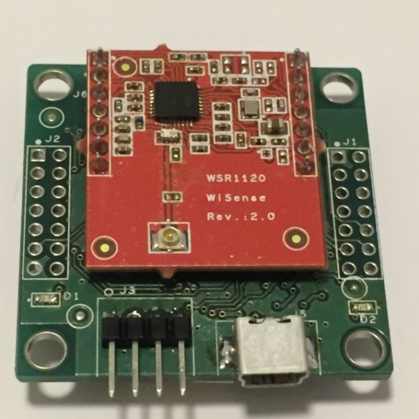
We reduced the size of the radio boards on our WSN1120L and WSN1120CL nodes. The earlier version (WSR1120 Rev 1.0) of the radio board had both a U.FL connector and a PCB antenna. The new version (WSR1120 Rev 2.0) only has a U.FL connector. The dimensions of the new radio board are 27.5 mm x 27.5 mm. These radio boards use the CC1120 radio from TI.

WSN1120L with the new radio board (WSR1120 Rev 2.0)
WSN1120CL with the new radio board (WSR1120 Rev 2.0)

WSN1120L with the earlier version of the radio board (Rev 1.0)
For more information, please visit wisense.in.
Effect of temperature on WiSense nodes
All WiSense sensor nodes use low cost RF crystals for the radio (CC1120 or CC1101). The crystal oscillator generates the reference frequency for the radio’s frequency synthesizer, as well as clocks for the ADC and the digital part. For example, the WSN1120L/WSN1120CL nodes use a 32 MHz cystal (FA-128-32MHz from Epson).
If the crystal frequency is incorrect, the transmitter carrier frequency and the receiver LO frequency will also be incorrect. The crystal frequency error is due to initial tolerance, capacitive loading errors, ageing, and temperature drift.
Example: If the crystal frequency has an error of +/- X ppm (parts per million) the RF frequency also has an error of +/- X ppm. As an example, if the crystal error is say +10 ppm and the CC1120 is programmed for a carrier frequency of 866 MHz, there will be an error in the carrier frequency of 866 *(10^6)* 10 * (10^-6) = 8.66 kHz.
Carson’s rule states that nearly all (~98 percent) of the power of a frequency-modulated signal lies within a bandwidth “BWsig” where
BWsig = dr + 2*fdev
Where “dr” is the data rate and “fdev” is the frequency deviation around the carrier frequency.
If both the transmitter and receiver crystal accuracy is ±10 ppm and the CC11xx is
programmed for a carrier frequency of 866 MHz ,
BWchann > BWsig + 4 * XTALppm * fRF = BWsignal + 4*10*(10^-6)*866*10^6 Hz.
Let us take a narrow band application with raw data rate of 1.2 kbps using 2-GFSK modulation and frequency deviation of 4 kHz.
BWsig = 1200 + 2*4000 = 9.2 kHz
BWchann > 9.2 kHz + 4*8.66 kHz
BWchann > 34.64 kHz
You can easily see that the channel bandwidth requirement is dominated by the +/- 10 ppm crystal tolerance figure !. Note that as channel bandwidth (programmed as the RX filter bandwidth parameter in radios such as CC1101 and CC1120) increases, radio range decreases. So it is important to keep the channel bandwidth to the minimum required to carry the modulated RF signal.
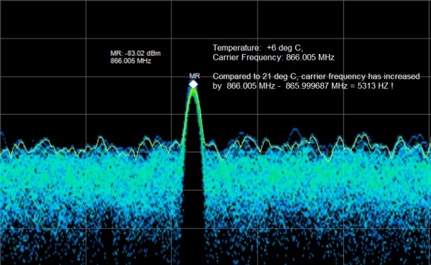
Temperature has a significant effect on crystal frequency. In our tests using WSN1120L nodes, we saw large carrier frequency drifts when subjected to different temperatures.
The snapshot below shows the carrier frequency (865.999687 MHz) at 21 deg C (room temperature).

The snapshot below shows the new carrier frequency (866.5 MHz) at 6 deg C (node inside a refrigerator)
Frequency drifts because of environmental conditions (such as temperature) are big problem for narrow band channels (channel bandwidth around 25 kHz or less). If channel spacing is low, RF signal on adjacent channels can overlap. Frequency drift between two nodes (on the same channel) can cause the nodes to loose communication if the transmissions fall outside the programmed RX filter bandwidth (on each node).
In narrow band radio devices (such as WiSense nodes) are installed outdoors, they should be inside weather proof enclosures to minimize frequency drift due to environmental conditions.
One approach is to use a temperature sensor mounted near the RF crystal and tune the radio carrier frequency based on the temperature.
Another (more complicated) approach is to use a tighter tolerance crystal on the coordinator node’s radio and let the other nodes in the network track the coordinator’s frequency using the CC11XX automatic frequency compensation feature.
Why not use crystals with tighter tolerance across a wide temperature range? The simple reason is cost.
The CC1120 radio supports low cost crystals (32 MHz) as well as temperature compensated crystal oscillators (32 MHz TCXO). On the CC1120, either a crystal can be connected to XOSC_Q1 and XOSC_Q2, or a TCXO can be connected to the EXT_XOSC input. The problem is that a TCXO can cost more than the total cost of a WSN1120L/WSN1120CL node !!.
References:
- https://e2e.ti.com/support/wireless_connectivity/proprietary_sub_1_ghz_simpliciti/f/156/p/470774/1691274
- https://e2e.ti.com/support/wireless_connectivity/low_power_rf_tools/f/155/t/180039
- https://en.wikipedia.org/wiki/Frequency_modulation#Modulation_index
- CC1120 data sheet (www.ti.com)
- https://www.eea.epson.com/wp-content/uploads/2016/09/September-2016-PCS-MASTER-BOOK.pdf
- http://www.mouser.com/ds/2/137/A-128_en-931416.pdf
- http://www.ti.com/lit/an/swra122c/swra122c.pdf
- http://electronicdesign.com/analog/minimize-frequency-drift-crystals
WiSense Radio Configuration
The CC1120 radios on the WSN1120L and WSN1120CL are configured to operate in the 865-867 MHz license free band in India. The modulation used is GFSK (Gaussian FSK). The data rate is configurable (example – 1.2 kbps, 10 kbps, 20 kbps and so on). Higher data rate translates to higher channel bandwidth (receiver filter bandwidth) which translates to higher channel noise (lower SNR) seen in the receiver resulting in reduced range.
Carson’s rule states that nearly all (~98 percent) of the power of a frequency-modulated signal lies within a bandwidth “BWsig” where
BWsig = dr + 2*fdev
Where “dr” is the data rate and “fdev” is the frequency deviation around the carrier frequency.
Taking into consideration crystal inaccuracy, the minimum channel bandwidth “BWchann” required comes to –
BWchann > BWsig + 4*XTALppm*fRF
-Or –
BWchann > dr + 2*fdev + 4*XTALppm*fRF
where “XTALppm” is the total accuracy of the crystal including initial tolerance, temperature drift, loading, and ageing.
and
“fRF” is the carrier frequency which will be 866 MHz (at the center of the 865-867 MHz license free India band) in our application.
Modulation index for FSK modulation (h) is given by –
h = 2*fdev / dr
for example, if deviation is +/- 4 kHz and the data rate is 1.2 kbps, then the modulation index is (2*4000) / 1200 = 6.666.
The chosen frequency deviation “fdev” will impact sensitivity and occupied bandwidth in opposing directions. For a fixed RX filter BW and data rate, higher deviation will give better sensitivity;
Theoretically, there is an optimum separation/data-rate setting if you simultaneously minimize the receiver filter bandwidth. Every halving of receiver filter bandwidth increases sensitivity with 3 dB whereas sensitivity vs separation/data-rate decreases with about 1.5-2.5 dB per halving down to a certain limit where the loss increases very fast.
The CC1120 operates well at modulations indexes of 0.5 and above.
Let us look at some settings for the CC1120 Radio in a WiSense LPWMN node.
Crystal specs
- Crystal frequency: 32 MHz
- Crystal tolerance: +/- 10 ppm @ 25 deg C
- Crystal operating range: -40 deg C to +85 deg C
- Crystal frequency vs temperature variation: +/- 20 ppm
- Crystal frequency aging: +/- 1 ppm per year (max)
Setting #1:
Radio configuration
- Modulation: 2-GFSK
- Bits per symbol: 1
- Data Rate: 1.2 kbps
- Frequency Deviation: +/- 3.997803 kHz
- Carrier frequency: 865-867 MHz
- Channel BW (RX filter BW): 25 kHz
- Feedback to PLL feature: Enabled
BWsig = 1200 + 2*3998 = 9196
Taking crystal inaccuracy (+/- 10 ppm) in consideration,
BWchann = 9196+ 4*10*(10^-6)*866*(10^6)
BWchann = 43836 Hz or 43.84 kHz
Modulation index = (2*3998) / 1200 = 6.66 (Minimum for CC1120 is 0.5, higher the better)
TI recommended setting for this configuration is 25 kHz which is less than 43.84 kHz. The CC1120 has a feature called feedback to PLL (F2BPLL) which increases the effective RX filter bandwidth without degrading the noise bandwidth and hence the sensitivity. Feedback to the PLL “increases the RX filter” and thus allow for a less accurate crystal to be used. The noise bandwidth, and hence sensitivity, will not increase when enabling this feature. Enabling feedback to PLL increases BW from “programmed RX filter BW” to “programmed RX filter BW +/- RX filter BW/4”. For example, when RX filter BW is configured as 25 kHz, the effective RX filter BW increases to 25 + (25/2) = 37.25 kHz. The only downside of using the F2BPLL is the need for a longer preamble length (of 4 bytes) instead of say just 2 bytes.
For best sensitivity we need to use the lowest RX filter BW possible. So an effective RX filter BW of 37.25 kHz is a good compromise for this application.
In addition, each WiSense node’s carrier frequency frequency error (due to the crystal’s initial crystal tolerance of +/- 10 ppm) is removed by
- Configuring the radio to output an un-modulated continuous wave (CW) signal and
- Using a spectrum analyzer to accurately measure the frequency of this CW signal and thereby the offset from expected value and
- Configuring the static frequency offset register on the radio with the offset measured above
- This offset frequency value (in HZ) is stored on each node in an EEPROM
Now any variation from desired frequency will only be because of temperature changes and aging.
Setting #2:
Radio configuration
- Modulation: 2-GFSK
- Bits per symbol: 1
- Data Rate: 10 kbps
- Frequency Deviation: +/- 5.004883 kHz
- Feedback to PLL feature: Enabled
- Channel BW (RX filter BW): 25 kHz
- Carrier frequency: 865-867 MHz
BWsig = 10000 + 2*5005 = 20010 HZ
Taking crystal inaccuracy (+/- 10 ppm) in consideration,
BWchann = 20020 + 4*10*(10^-6)*866*(10^6)
BWchann = 54660 = 54.6 kHz
Modulation index = (2*5010) / 10000 = 1.002 (Minimum for CC1120 is 0.5)
Since feedback to PLL feature is enabled, effective rx filter bw is 25000 * 1 .5 = 37.5 kHz.
In addition, the carrier frequency frequency error (due to the crystal’s initial crystal tolerance of +/- 10 ppm) has been removed as explained above. We tested this configuration and it is working well.
Setting #3:
Radio configuration
- Modulation: 2-GFSK
- Bits per symbol: 1
- Data Rate: 20 kbps
- Frequency Deviation: +/- 10.009766 kHz
- Channel BW (RX filter BW): 50 kHz
- Feedback to PLL feature: Enabled
- Carrier frequency: 865-867 MHz
BWsig = 20000 + 2*10009 = 40020 HZ
Taking crystal inaccuracy (+/- 10 ppm) in consideration,
BWchann = 40020 + 4*10*(10^-6)*866*(10^6)
BWchann = 74660 = 74.6 kHz
Modulation index = (2*10009) / 20000 = 1.0009 (Minimum for CC1120 is 0.5)
Since feedback to PLL feature is enabled, effective bandwidth is 40020 * 1 .5 = 60.03 kHz.
In addition, the carrier frequency frequency error (due to the crystal’s initial crystal tolerance of +/- 10 ppm) has been removed as explained above. We tested this configuration and it is working well.
References:
- https://e2e.ti.com/support/wireless_connectivity/proprietary_sub_1_ghz_simpliciti/f/156/p/470774/1691274
- https://e2e.ti.com/support/wireless_connectivity/low_power_rf_tools/f/155/t/180039
- https://en.wikipedia.org/wiki/Frequency_modulation#Modulation_index
- CC1120 data sheet (www.ti.com)
- https://www.eea.epson.com/wp-content/uploads/2016/09/September-2016-PCS-MASTER-BOOK.pdf
- http://www.mouser.com/ds/2/137/A-128_en-931416.pdf
- http://www.ti.com/lit/an/swra122c/swra122c.pdf
