Borewell water level monitoring using time slotted star network of LORA radios.
One of our customers needed to monitor the water level in multiple borewells spread over a large area with heavy vegetation and uneven terrain. They tried LoRAWAN over a period of 3-4 years but could not get it to work reliably.
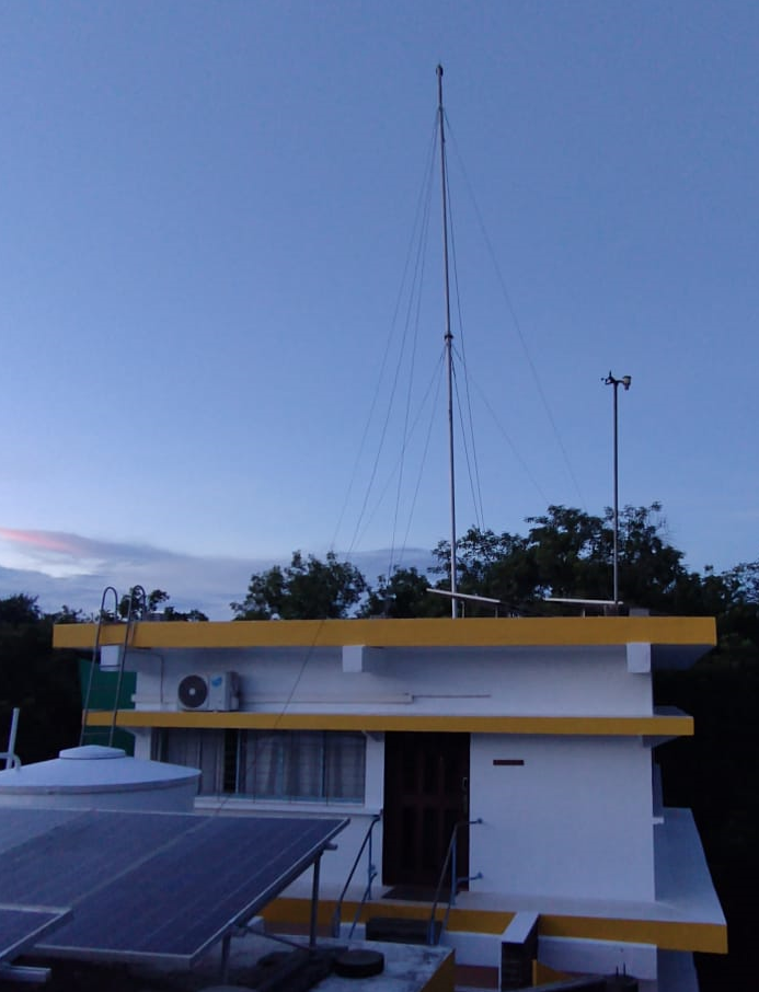
WiSense has developed an economical wireless sensing and control solution which employs a time slotted star network of LORA radios with a low cost single channel LoRA + WiFi gateway at the center.
Since our gateway is low cost, multiple such star networks can replace a single expensive multi channel gateway with all the bells and whistles.
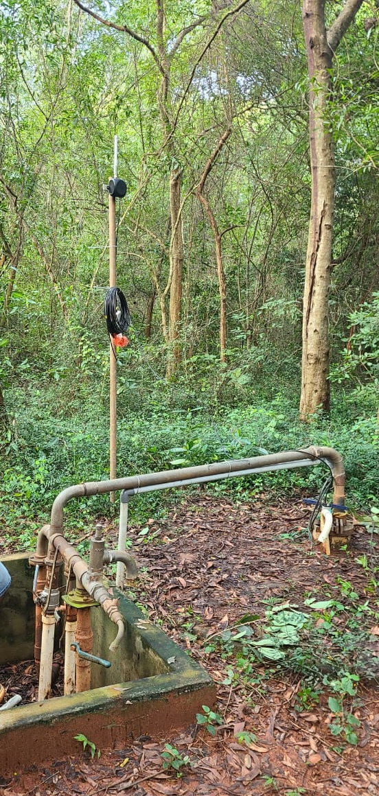
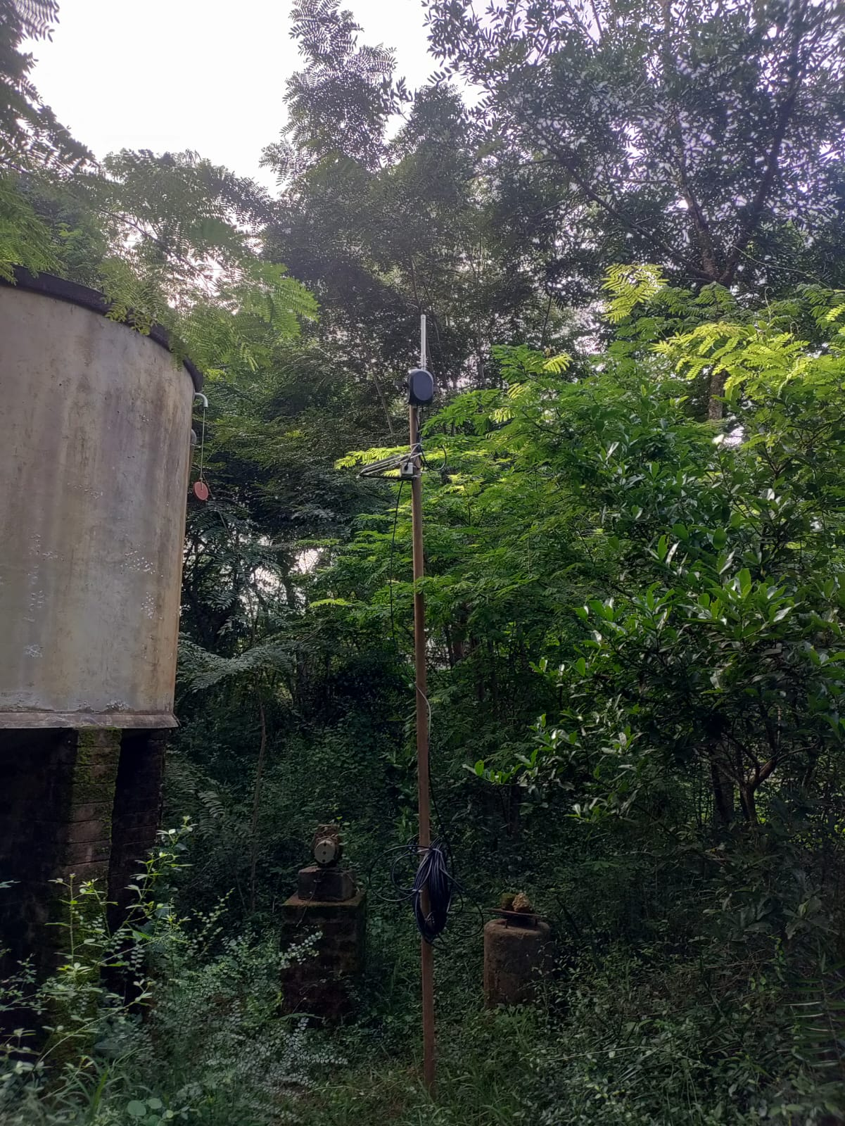
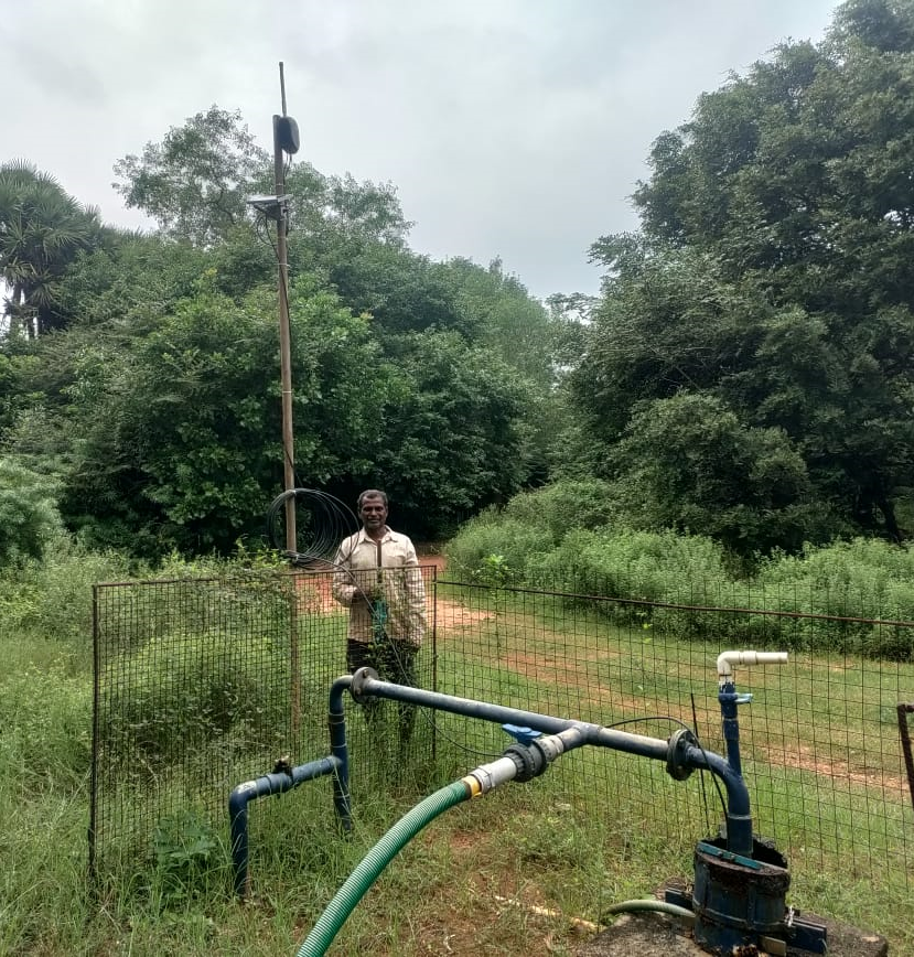
We have deployed 3 separate star networks for this customer, each receiving data from borewells in the vicinity.
We integrated our general purpose wireless sensor nodes with borewell sensors previously bought by the customer.
Borewell water level monitoring involves comparatively higher data traffic since changes in water levels due to pumping and subsequent natural in flow can all happen in a matter of minutes. It is important to capture these events. Our star network is time slotted to avoid collisions between different nodes sending data to the same parent gateway.
The time slotted star network has dedicated uplink and downlink slots for each sensor node allowing collision free bi-directional communication with each sensor node. This allows easy reconfiguration of sensor node behavior.
Max transmit power is +22 dBm. We could get up to 1.5 km range through dense vegetation.
The sensor nodes are all solar powered. We offer a solar li-ion charger power supply PCB which also includes a couple of V/I sensors to monitor solar and battery voltage/currents at all times.
Each data packet sent by a sensor node includes the following information:
- 64 bit IEEE assigned globally unique id/address
- Borewell water level in mm
- Li-Ion battery voltage in mV.
- Li-Ion battery current in mA (negative value when discharging, positive value when charging)
- Solar panel voltage in mV.
- Solar panel current in mA
- A 32 bit message sequence number
- Data transmission interval in seconds
.
.
.
.
.
.
.
.
One of the gateways mounted on top of a tall pole
.
.
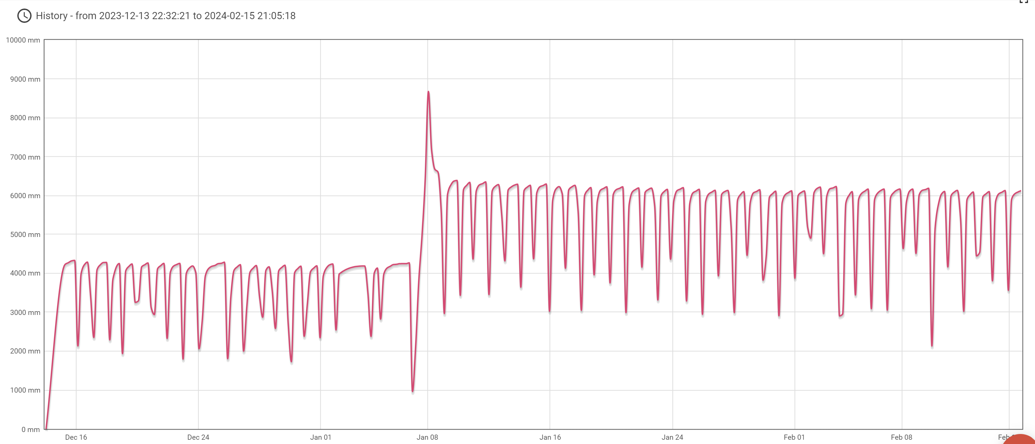
Snapshot of borewell water level chart taken from sensor dashboard hosted on AWS
.
.
.
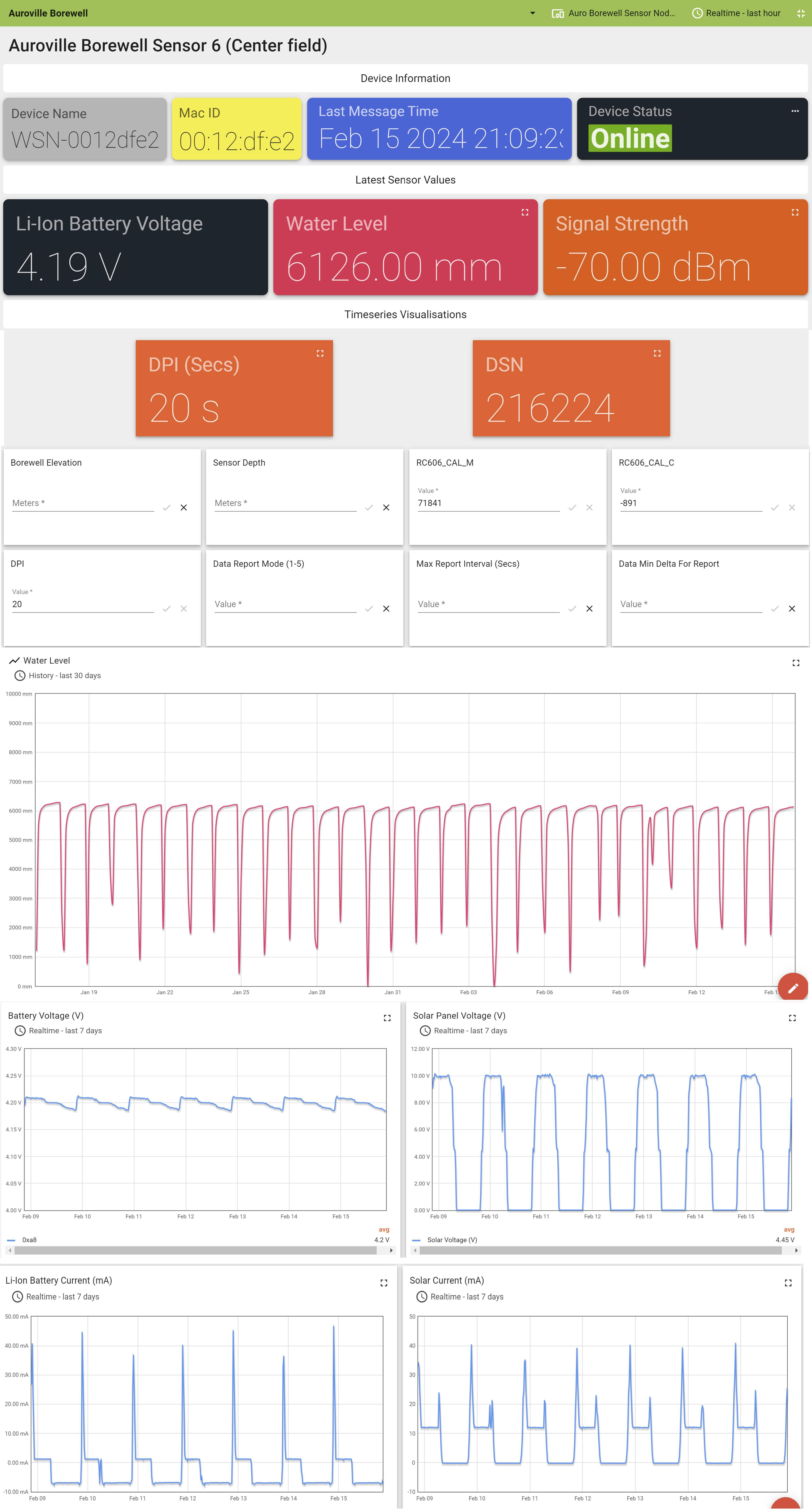
Snapshot of a specific borewell sensor node’s dashboard hosted on AWS
WEM110-1P-SEL1 for Cold Storage Energy Monitoring
This is another component of our cold chain monitoring solution. This product monitors the power, current, voltage, frequency, power factor and energy consumption of a refrigerator in real time. All this data is sent to the cloud via a WiSense Gateway.


This product uses an off the shelf single phase energy meter. The wireless node periodically retrieves data from the energy meter over a Modbus/RS-485 connection and sends it to the associated cloud dashboard via a WiSense gateway.
The wireless node is powered by mains power through a 3W AC/DC module. The node operates in FFD mode where the radio is always on allowing it to act as a data source as well as a router for other nodes in the WiSense Sub-GHz network.
Sub-GHz Radio
Multiple geographies supported:
- FCC (900 MHz band) certified Radio
- ETSI (868 MHz band) certified Radio
- India (865-867 MHz band) compliant Radio
Customization
Apart from the radio variant, we support customization of the enclosure, antenna, energy meter etc. In addition, the application level firmware running on the wireless node can be modified to support any reporting interval, any combination of parameters to report, alerts on basis of configured thresholds on power, current, voltage, frequency, power factor etc.
WiSense Gateway
The WiSense gateway has multiple interfaces such as WIFI, RS-232, RS-485, serial over USB.
The gateway will forward data received from network nodes to a configured endpoint which can be local or in the cloud. Supported standards/formats include MQTT, JSON, HTTP, HTTPS etc.
A single gateway can support up to 64 sensor nodes of different types. Each sensor node has a IEEE assigned globally unique 64 bit MAC address. Each sensor on a sensor node has a unique 8 bit ID.
The WiSense low power sensor node network supports both mesh and star configurations.

WDN110 Wireless Door Sensor
The WDN110 is a wireless door sensor operating in the Sub-GHz band. It is powered by two AAA batteries. Sleep mode power consumption is less than 2 microamps.
Multiple geographies supported:
- FCC (900 MHz band) certified Radio
- ETSI (868 MHz band) certified Radio
- India (865-867 MHz band) compliant Radio

This sensor node report’s the state of the door (open or closed). It runs on 2 AAA batteries which can last many years since the node stays in ultra low power mode consuming a few microwatts except when it has to communicate with the associated network gateway.
Sensing Element
The door sensor utilizes an SPDT (Single Pole Double Throw) reed switch which opens or closes under the influence of a magnetic field. The SPDT configuration makes the sensor more power/energy efficient compared to door sensors which use a SPST (Single Pole Single Throw) reed switch.

The SPDT reed switch enclosure is 3D printed. It connects to the sensor node PCB over a three wire cable. This connection is ESD protected.
We also offer a single sensor node with temperature, RH and door sensors.
Installation
- Open the node enclosure, insert two AAA batteries and close it.
- Stick the magnet on the edge of the door frame. It should be placed vertical to the ground.
- Stick the switch on the edge of the door as close as possible to the magnet.
- Place the node enclosure as high as possible with the antenna perpendicular to the ground.
- Switch on the node. It will automatically connect to the gateway and start sending whenever the door is opened or closed.
Reporting Algorithm/Logic
The firmware on the sensor node runs can be configured to :
- Report every time the door opens or closes.
- Report only when the door is left open for more than a (configurable) duration. In this case, the node will send door state report at a higher frequency until the door is closed.
- If the door state does not change for a long time, the node can be additionally configured to send a report conveying the current state of the door after a configurable interval of inactivity. This message then serves as a keep-alive indication to the end application (local or cloud resident).
If the node is being used to monitor say a refrigerator or freezer, the door sensor reports will be useful in explaining changes in measured temperature.
Note that each report message also includes the supply voltage from the two batteries (connected in series).
WiSense Gateway
This node sends door state change alerts via a WiSense gateway. This gateway has multiple interfaces such as WIFI, RS-232, RS-485, serial over USB.
The gateway will report the door state to the configured endpoint which can be local or in the cloud. Supported standards/formats include MQTT, JSON, HTTP, HTTPS etc.
A single gateway can support up to 64 sensor nodes of different types. Each sensor node has a IEEE assigned globally unique 64 bit MAC address. Each sensor on a sensor node has a unique 8 bit ID.
The WiSense low power sensor node network supports both mesh and star configurations.

For more information, visit wisense.in.
WTN300: Wireless Cold Chain Temperature/RH Sensor
The WTN300 is a wireless temperature/RH sensor node operating in the Sub-GHz band. It is powered by two AAA batteries. Sleep mode power consumption is less than 2 microamps.
Multiple geographies supported
- FCC (900 MHz band) certified Radio
- ETSI (868 MHz band) certified Radio
- India (865-867 MHz band) compliant Radio
This node talks to a WiSense gateway with WIFI, RS-232, RS-485, serial over USB simple UART interface.
The node supports three different types of temperature sensors
- DS18B20 over I2C link (-55 deg C to + 50 degrees C)
- PT-100/PT-1000 (-100 deg C to +50 degrees C)
- TMP102 for ambient air sensing (-5 to +50 degrees C)
It uses the HIH8120 for relative humidity.
Installation is simple. Insert two AAA batteries and switch on the node. It will automatically connect to the gateway and start sending data. The gateway will send data to the configured endpoint which can be local or in the cloud. Supported standards/formats include MQTT, JSON, HTTP, HTTPS etc.

.

.

.

.

Y-axis is temperature in degree C while X-axis is time.
For more information on WiSense products, please visit wisense.in.
Real Time Coastal Wave Monitor
WiSense developed this prototype for a university in the US. The prototype uses a high resolution pressure sensor to determine wave height and report the same to the cloud in real time. This is intended to replace currently available instruments which log data but do not have radio connectivity to report the data in real time.
We used a LTE CAT1 modem to report the sensor data sampled at 16 Hz. LTE CAT-M and LTE NB-IOT radios are meant for applications which need to communicate infrequently like a water meter which sends a small message every hour or just once every day.
As can be seen in the pics below, the sensor node has two distinct parts – the sensing module and the comms module which are connected by a cable which can be up to 50 meters long.
Sensing Module
- Analog pressure sensor with exposed diaphragm
- Signal conditioning circuitry
- RS-485 Transceiver
- Waterproof Stainless steel enclosure
- Waterproof cable connection
Comms Module
- STM32 Microcontroller
- RS-485 Transceiver
- LTE CAT1 Radio
- Weather proof LTE Antenna
- LI-Po battery
- Atmospheric pressure sensor
- IP67 Enclosure
- Provision for external power supply
- Waterproof cable connection
The connecting cable has three functions.
- As a tether
- Conveys power to the sensing module.
- RS-485 data link (Differential signaling suitable for long distances)


We designed the water-proof stainless steel enclosure from scratch. Here are some 3D renders of the enclosure. The enclosure was machined in Bangalore.


For more information on WiSense, please visit wisense.in.
WTM-4P-110 Update
This is a brief follow up post on the WiSense WTM-4P-110 sensor node designed specifically for wirelessly monitoring the temperature of the cocoa bean fermentation process.
Here is some data from a customer site showing the temperature profile during the fermentation process. The data is from April 30 to May 4 (5 days).

The temperature data shown above is from one of the four sensor probes on the wireless node.
The graph below is showing data from all four sensor probes (inserted in to the same fermentation box).

The graph below is showing the battery voltage over the same period of 5 days. The node is powered by 2 AA batteries. The variation is less than .05 volts even though this node was sending data of all four sensor probes every 1 minute.

See below, a typical fermentation box.

For more information on WiSense products, please visit wisense.in.
See the original post here – https://wisense.wordpress.com/2021/02/07/wtm-4p-110-wisense-wireless-sensor-node-for-monitoring-temperature-during-cocoa-bean-fermentation/
WMB11X-20: WiSense Gateway with ModBus Interface
Here are some pics of the latest version of our Low Power Wireless Mesh Network (LPWMN) gateway with ModBus Interface.


Sub-GHz Radio Options
| FCC | USA | 902-928 MHz |
| ETSI | EU | 868-870 MHz |
| WPC | India | 865-867 MHz |
| Non Certified | Any | Any available ISM Band |
For more information on WiSense products, please visit wisense.in
WTM-4P-110 – WiSense Wireless Sensor Node for Monitoring Temperature during Cocoa Bean Fermentation
Our latest product enables Cocoa processors to monitor in real time the temperature of Cocoa beans during the fermentation process.

.
.

(Courtesy ecus@https://3dwarehouse.sketchup.com/)
.
.
Specifications
| Component | Specs | Options |
| Controller | Ultra low power 16 bit Microcontroller (TI MSP430G2955) | Can be upgraded to MSP430F419A or any other variant. |
| Radio | Sub-GHz ISM Band Low Power Radio ❏ India: 865 to 867 MHz ❏ EU: 868 – 870 MHz ❏ USA: 902 – 928 MHz > Multiple raw baud rates supported such as 1.2 kbps, 10 kbps, 20 kbps, 38.4 kbps, 100 kbps > Modulation: 2FSK / GFSK > Tx Power: Max 13 dBm > Note that supported baud rates, modulation, bandwidth, duty cycle and max transmit power are subject to local ISM band regulations (ETSI / FCC / WPC etc) | Certified (FCC/ETSI) and non-certified radio module options available. |
| Antenna | Omni Directional Half Wave Dipole External Antenna Gain: +3 dBi gain | PCB Antenna / Internal stick-on Antenna with U.Fl connector or any other suitable Antenna. |
| Power Supply | 2 x AA batteries | Other options available > 2 x AAA > Li-Ion |
| Enclosure | ABS | Changeable on request |
| Temperature Sensor | > Sensor Count: Min 1, Max 4 > ±0.5°C Accuracy from -10°C to +85°C > Overall Range: -55°C to +125°C > Probe Length: 200 mm (Can be made shorter or longer) | Changeable on request |
| On/Off Switch | Mounted on the enclosure | Changeable on request |
| Sleep Mode Power Consumption | < 2 Microamps | |
| Reporting Interval | From every 1 second to once a day. | Configurable (any time) from the cloud |
| Sensor Node Identifier | Unique IEEE assigned 64-bit address hardwired in onboard EEPROM Ex: fc:c2:3d:0x00:00:11:0a:1e (all Hex) |
.
.
| Temperature Data Reporting Options | |
| 1 | Reports measured temperature periodically with a configurable interval – Minimum (1 sec) / Maximum (1 day). |
| 2 | Reports measured temperature only when it changes by a configurable percentage value with respect to the prior value reported. Also, reports measured temperature if no report sent for a configurable period of time. |
| 3 | Reports measured temperature only when it crosses a configurable high or low threshold value. High and low hysteresis values are also configurable. Also, reports measured temperature if no report sent for a configurable period of time. |
| 4 | WiSense can implement any custom temperature reporting algorithm. |
.
.
| Each sensor data message sent by a sensor node to the cloud (via a WiSense Gateway) conveys the information listed here – | |
| 1 | IEEE assigned 64 bit permanent address of the node (Ex: 0xfc:0xc2:0x3d:0x00:0x00:0x1e:0xf5) |
| 2 | Battery Voltage (Milli-Volts) |
| 3 | Sensor Probe #1 Id: 0x6c Temperature: Measured Value (milli-deg C) |
| 4 | Sensor Probe #2 Id: 0x96 Temperature: Measured Value (milli-deg C) |
| 5 | Sensor Probe #3 Id: 0x97 Temperature: Measured Value (milli-deg C) |
| 6 | Sensor Probe #4 Id: 0x98 Temperature: Measured Value (milli-deg C) |
.
.

The graph shows data from all 4 sensors.
.
.

Collects data from up to 64 sensor nodes and relays to the cloud over WiFi (Other backhaul technologies supported)
.
.
For more information on WiSense products, please visit wisense.in.
Wireless Incubation Sensor – Data

measuring ambient temperature in close vicinity
The graph above shows the ambient temperature measured by seven thermistors on a single sensor egg. Note that the temperature readings are very close to each other as should be because they are all close to each other and measuring the ambient temperature.
The data for this graph was downloaded from the WiSense cloud resident data collection and visualization platform.
The setup has one sensor egg (with seven thermistors) sending data to the cloud (via a WiSense gateway) periodically every 30 seconds. Total of 2880 sensor data messages were sent over a period of 24 hours. Each sensor data message also conveys the voltage of the Li-Ion battery inside the sensor egg.
.

Starting Battery Voltage: 3.94V. Battery Voltage after 24 hours: 3.93V
After sending 86400/30 = 2880 messages, the battery voltage has dropped by only 0.01 V.
.
For information on WiSense products, please visit wisense.in.
